Imagine a silent, invisible threat lurking within your solar power system. It’s not a physical flaw you can see, but a gradual degradation of the protective barrier around high voltage wires. This threat can lead to catastrophic failures, fires, or even lethal electric shocks. The only way to find it? Insulation resistance testing in inverters. This isn’t just a routine check up; it’s a critical diagnostic that stands between a safe, efficient system and a potential disaster. As the adoption of solar power continues to grow worldwide, ensuring the safety and reliability of PV systems is more crucial than ever.
Key Takeaways
- The PV system’s array insulation resistance monitoring function serves to reduce the risk of electric shock or fire caused by DC side ground faults.
- The test uses high DC voltage to measure resistance, identifying weak spots before they fail.
- Regular testing can save thousands in repair costs and prevent system downtime.
- It’s a non negotiable requirement in most electrical codes and for maintaining warranties. Example IEC 62109-2 for inverters and IEC 60364-7-712 for PV installations.
Why Your Inverter’s Insulation is Its Unsung Hero
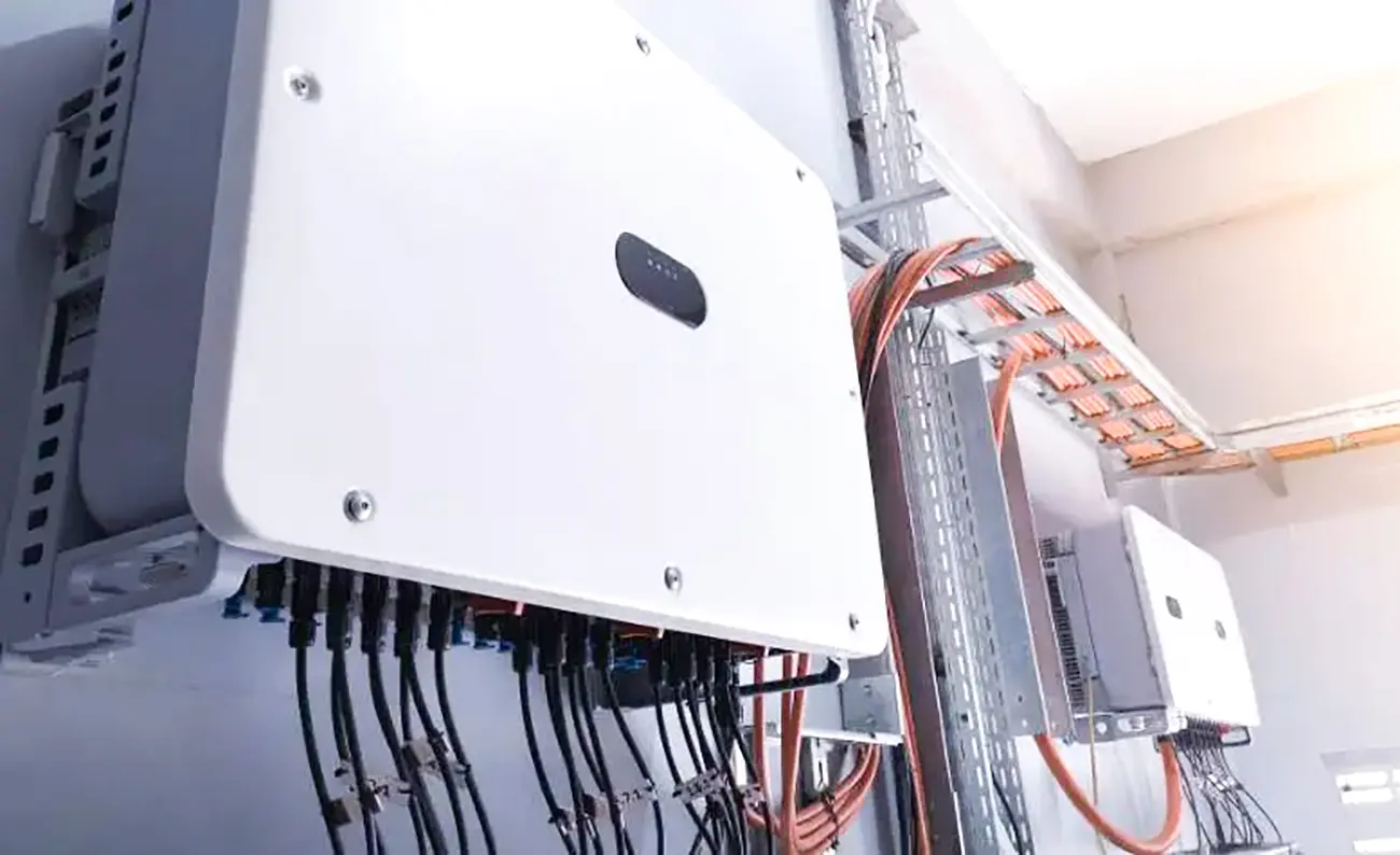
An inverter’s job is to convert high voltage Direct Current (DC) from your solar panels into usable Alternating Current (AC). Those DC wires carry a significant amount of power. The insulation, the colored plastic coating on the wire is the only thing separating this potent energy from the grounded metal components of the system, like the inverter chassis, mounting racks, and your roof.
Over time, this insulation can be compromised by:
- Heat: Constant thermal cycling under the sun.
- Moisture: Water ingress or damp condensation in junction box due to not properly sealed junction box or DC isolator enclosure, which will lower the insulation resistance and cause an Insulation fault.
- Physical Damage: Abrasion, pinching, or pest chewing.
- Poor Installation: Damaged PV panels or DC wires, such as mounting screw through the back of a module .
- Chemical Exposure: Or from environmental pollutants.
When insulation fails, it creates a “ground fault”, a path for electricity to flow to the ground. This is where the danger lies.
The “How”: A Deeper Dive into the Megger Test
So, how does insulation resistance testing in inverters work? In simple terms, you’re stress testing the insulation. A specialized tool called a “megohmmeter” or “Megger” (a brand name that became generic) is used.
The process is methodical:
- Safety First: The system is completely shut down and isolated.
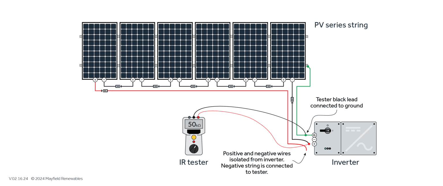
- Connection: The Megger is connected between the DC conductors (positive and negative combined) and the earth ground.
- Application of Voltage: The tool generates a high DC voltage (typically 500V or 1000V, as specified by the inverter manufacturer) and applies it across the insulation.
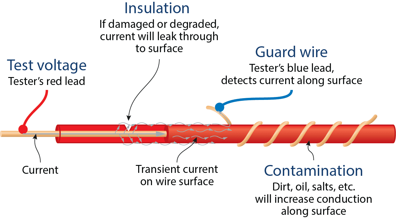
- Measurement: It measures the tiny current that inevitably “leaks” through the insulation. Good insulation will have very high resistance (measured in Megohms, MΩ), allowing minimal leakage. Poor insulation will have low resistance, allowing excessive current to flow.
Interpretation is Key: There’s no single “pass/fail” number. Standards like IEC 62109-2 for inverters and IEC 60364-7-712 for PV installations recommend a minimum value. However, an experienced engineer looks at trends. Based on Section 4.8.2.1 of IEC62109-2: the minimum set threshold of impedance should not be lower than R=Vmax PV/30mA. Where Vmax is the maximum inverter voltage on the DC side. If the value is too low, the inverter will issue an alarm and refuse to connect to the grid, preventing a dangerous situation.
The Inverter’s Built In Guardian: Continuous Insulation Monitoring
Beyond manual testing, modern inverters have a crucial built in feature: continuous insulation resistance monitoring. As the adoption of solar power grows worldwide, this automated function is the first line of defense, actively working to reduce the risk of electric shock or fire caused by DC side ground faults.
It’s vital to understand that an insulation fault alarm is not an inverter hardware failure. The inverter is simply detecting a problem elsewhere in the PV system. This failure can occur during initial installation or appear years later in a commissioned plant.
For non isolated inverters, a DC side ground fault can create a direct loop between the fault point and the electrical grid. The inverter’s monitoring function is designed to prevent this exact scenario.
The Fault Finder’s Checklist: What Causes Insulation Resistance Failure?
When an alarm triggers, where do you look? The culprits are often found in the array itself:
- Damaged Components: PV panels with cracked cells or DC wires pierced by a mounting screw or pinched against a rail.
- Water Ingress: Not properly sealed junction boxes, DC isolator enclosures, or connectors leading to damp condensation.
- Poor Connections: Aging or poor quality cable junctions between modules.
- Installation Errors: Damaged AC cables or insufficient clearance between live parts and grounding.
FAQ: Your Insulation Resistance Questions Answered
Q: How often should insulation resistance testing be performed?
A: It is mandatory after initial installation (commissioning) and should be repeated during major maintenance, typically every 1-3 years, or anytime a ground fault alarm is triggered.
Q: Can I perform this test myself?
A: No. This test involves high voltages and requires a certified electrician or solar technician with the correct equipment and training. Incorrect testing can damage the inverter’s sensitive electronics.
Q: My inverter has built in ground fault protection. Isn’t that enough?
A: The internal protection (including continuous monitoring and RCM) is a last line of defense, it often trips after a fault has already occurred or is imminent. Manual insulation resistance testing is a proactive measure that identifies the weakness before it becomes a dangerous fault.
Q: What’s the difference between this and a continuity test?
A: A continuity test (with a multimeter) uses a low voltage to check if a circuit is complete. An insulation resistance test uses high voltage to check how good the insulation is at blocking current. They are opposite tests.
This article is based on international standards (IEC 62446, IEC 62109-2) and industry best practices from reputable sources. Always consult a qualified professional for your specific system.
Sources:
- Solis, “Detecting and Preventing DC Insulation Short Circuits in PV Systems”
- EITAI Solar, “Power Generation” Technical Notes
- IEC 62109-2: Safety of power converters for use in photovoltaic power systems – Part 2: Particular requirements for inverters
- Three Common Faults in PV Inverters and Their Solutions
- Electrical Installations for Photovoltaic Solar Power System
Leave a Reply